Visualize a Project Design
Understanding your system and the interactions between software elements is critical for new integrations and safety. We use component-based design to try and make sense of this complexity. However, doing component-based design is a challenge in the absence of a Component Software Integration Platform (CSIP). That's why we made Tangram Pro™!
You'll learn how to:
- Design a component-based system
- Define component interfaces
- Connect components
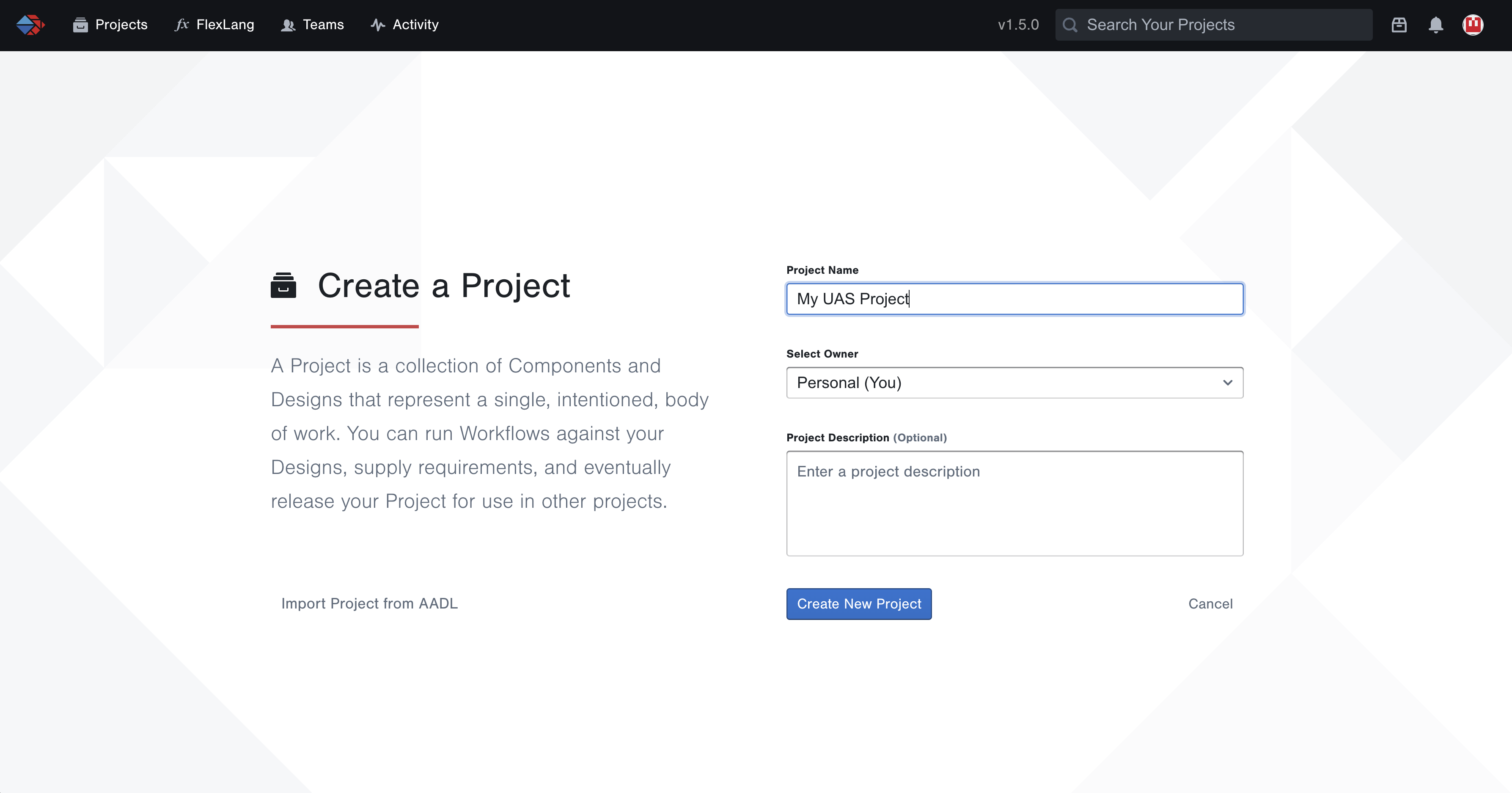
Step 1: Create a Project
To begin modeling a system we need to make a project. Projects are used to design component-based systems, and generate code based on your design. Each project is a reusable element that can stand alone as a single design, or be connected with other projects for extended capabilities. Let's get started!
- Go to Projects and click New Project
- Enter a Project Name
- You can associate a team to your project with the Select Owner dropdown menu. Let's keep
Personal (You)selected for now
After your project is created, you can go to Settings to update its name. Go to Members to add other users to your project to collaborate. For additional information see User Guide: Projects.
Step 2: Add a Component
Components are the basic building blocks of a system design. They represent pieces of software or hardware that communicate by sending and receiving messages. In this tutorial, we're going to model a simple unmanned aerial system (UAS). To start, let's add a component to represent a ground control station (GCS).
- Click the Add Component button
- Click anywhere on the stage to place it
- Change its name to GCS by double-clicking on the name
Step 3: Define a Component Interface
Each component has an Interface that specifies which messages it can send or receive. These interfaces are the points of connection and communication between components in your system.
There are two ways to define component interfaces in Tangram Pro™:
- Edit a component – This lets you explicitly define its interface, as well as lock it to prevent future changes.
- Connect a component to another one – This will infer its interface based on the component you connect to.
First we'll edit the GCS component and explicitly define its interface. We'll be using OpenUxAS LMCP formatted messages, but there are several built-in message standards available in Tangram Pro™.
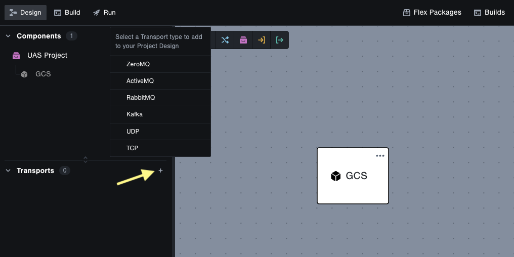
Define a Message Transport
- In the left sidebar, click the + button next to Transports
- Select ZeroMQ
Define the GCS Component Interface
- Click the ... icon in the GCS component and choose Messages
- Set the Interface Package to
OpenUxAS::LMCP::v3 - Select the following messages
AirVehicleStateAirVehicleConfigurationGimbalState
- Set the Message Direction to Input/Output
- Lock its interface by clicking the Unlock/Lock toggle button
- Press the escape key or click anywhere on the stage to close the component details
Nice work! You've created your first component and defined its interface. Next we'll look at making connections.
Step 4: Connect and Infer Interfaces
The next components you create will infer their interfaces based on connections. There are 3 more components needed to complete the project design. Let's get started!
Add a Communications Component
- Add a component and name it
Communications - Draw a connection from
GCStoCommunicationsby clicking and dragging from the edge ofGCS - Specify the messages included in the connection by clicking on the connection line. Note: The ZeroMQ transport you added earlier is applied to all connections by default.
- Click into Search Messages and select all three messages
- Click Switch Directions and select all three messages
- Click the Done button
Communications and GCS are now connected across a common interface. They are designed to send and receive the same messages. Two more components to go!
Add a Navigation Component
- Add a component and name it
Navigation - Draw a connection from
CommunicationstoNavigation - Edit the connection, click the Suggested button, and choose the following messages:
AirVehicleStateAirVehicleConfiguration
- Click Switch Directions, click the Suggested button, and choose the following messages:
AirVehicleStateAirVehicleConfiguration
- Click Done or anywhere on the stage to close the component details
Add a Payload Component
- Add one more component and name it
Payload - Draw a connection from
CommunicationstoPayload - Edit the connection, click the Suggested button, and choose the following messages:
GimbalState
- Click Switch Directions, click the Suggested button, and choose the following messages:
GimbalState
- Click Done or anywhere on the stage to close the component details
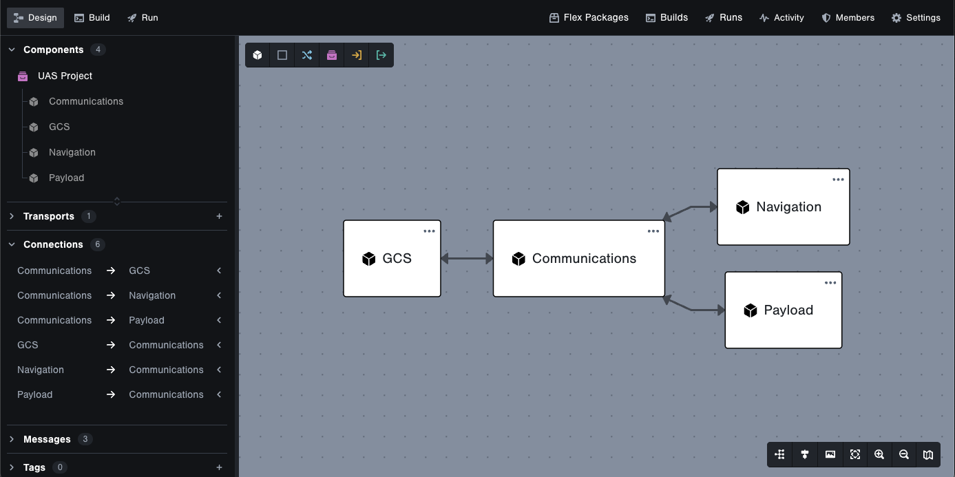
Navigation and Payload are now connected to Communications. Their interfaces include a subset of messages from the Communications interface.
Your completed design should look similar to this
Step 5: Explore Your Design
Great work building your first system! Let's take a look at a couple more areas.
Adjusting the View
You can change the direction and alignment of connections, and zoom in and out using the toolbar on the bottom right. There's also an Export button to save your design as an image or PDF.
Additionally, you can group components together and add tags to clearly label and organize your design. For more information see User Guide: Design.
View Connections Overview
The left sidebar has a Connections section which lists each connection in your design. You can expand a connection to see which messages are included. Hover over a connection or message to highlight it in the design.
Cheers!
By completing this tutorial, you've learned to design your first component-based system with Tangram Pro™!
Check out what you accomplished:
- Created a project
- Designed a system of components that communicate with OpenUxAS LMCP messages
- Defined component interfaces
- Locked a component interface
- Created connections between components
If you want to know more about component-based system design in Tangram Pro™, take a look at our blog posts.
Ready to generate some code with a Tangram Pro™ Build? Head on over to the next tutorial below!