Verifier: Test a Software Component
This tutorial focuses on the Verify tool in Tangram Pro™. Verify allows you to run a software component in a container, and test it against a message sequence model so you can be more confident that your software is doing what it's supposed to do. We made this tool to help streamline the verification of software behavior, in an online collaborative workspace that links a component in a system design to actual software and user-defined test sequences.
You'll learn how to:
- Configure a software component and test environment
- Define test sequences and constraints
- Configure and run tests
What software will be tested in this tutorial?
- We provide example source code in GitHub of a C++ software component one might find on a mission-critical UAV, albeit a simplified version for demonstration purposes, that processes mission commands.
- This source code utilizes Tangram Pro-generated interface libraries that enable processing messages defined by the OpenUxAS LMCP standard and communicating over a ZeroMQ transport.
What behavior will be tested in the example software component?
The software is expected to handle these two mission sequences:
- A) When it receives a
MissionCommandmessage, a sequence of messages expected to happen - B) When it receives a
CameraActionmessage, a different sequence of messages is expected to happen
Additionally, there are specific values or ranges of values that are expected within these messages. Tangram Pro can help verify those as well!
Step 1: Connect to GitHub
Your Tangram Pro account can pull containers from GitHub and GitLab registries to run software executables and container images. For this tutorial, we provide example source code in GitHub.
A GitHub account is required to complete this tutorial. If you do not have one, please go to https://github.com/ to set one up.
Once you've confirmed your GitHub login, go ahead and connect your Tangram Pro account to it:
- In Tangram Pro, go to Account by clicking your avatar image in the upper right corner of the page
- Scroll down to Source Code and click Add Hosting Service
- Choose GitHub.com
- Click the Register an OAuth App link to open GitHub
- Follow these instructions to complete the integration
Now you'll be able to link GitHub repositories to components in Tangram Pro. We'll do that in a later step.
Step 2: Create a Project
To get started create a new project:
- Go to Projects and click New Project
- Enter a Project Name
- Select your account for Owner
Step 3: Add a Transport
Add a transport (or networking) library to your project. The example software component requires the ZeroMQ library to send and receive messages. Let's add it:
- Find Transports on the lefthand side and click the + button
- Choose ZeroMQ
Step 4: Add a Component
The example software is expected to be able to process a specific subset of LMCP formatted messages. Let's add those to a component.
Add a single component:
- Click the Add Component button
- Click anywhere on the stage to place it
- Double-click on the component's name and change it to "MissionComputer"
Define the component's interface:
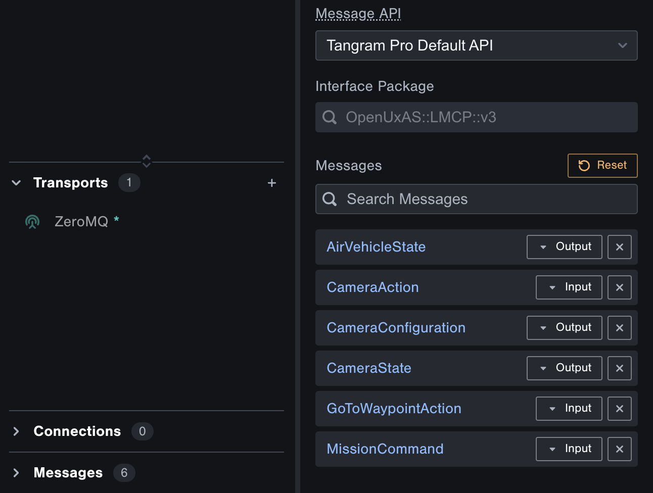
- Click the component's ... menu, and select Messages. Here you can choose the Flex Package, and the Messages that will be input or output from the component.
- Click into Search Packages and select
OpenUxAS::LMCP::v3 - Click into Search Messages and select the following:
AirVehicleStateCameraActionCameraConfigurationCameraStateGoToWaypointActionMissionCommand
- Change these three messages to be an Output
AirVehicleStateCameraStateCameraConfiguration
Your component messages should look like this:
Step 5: Configure Repository
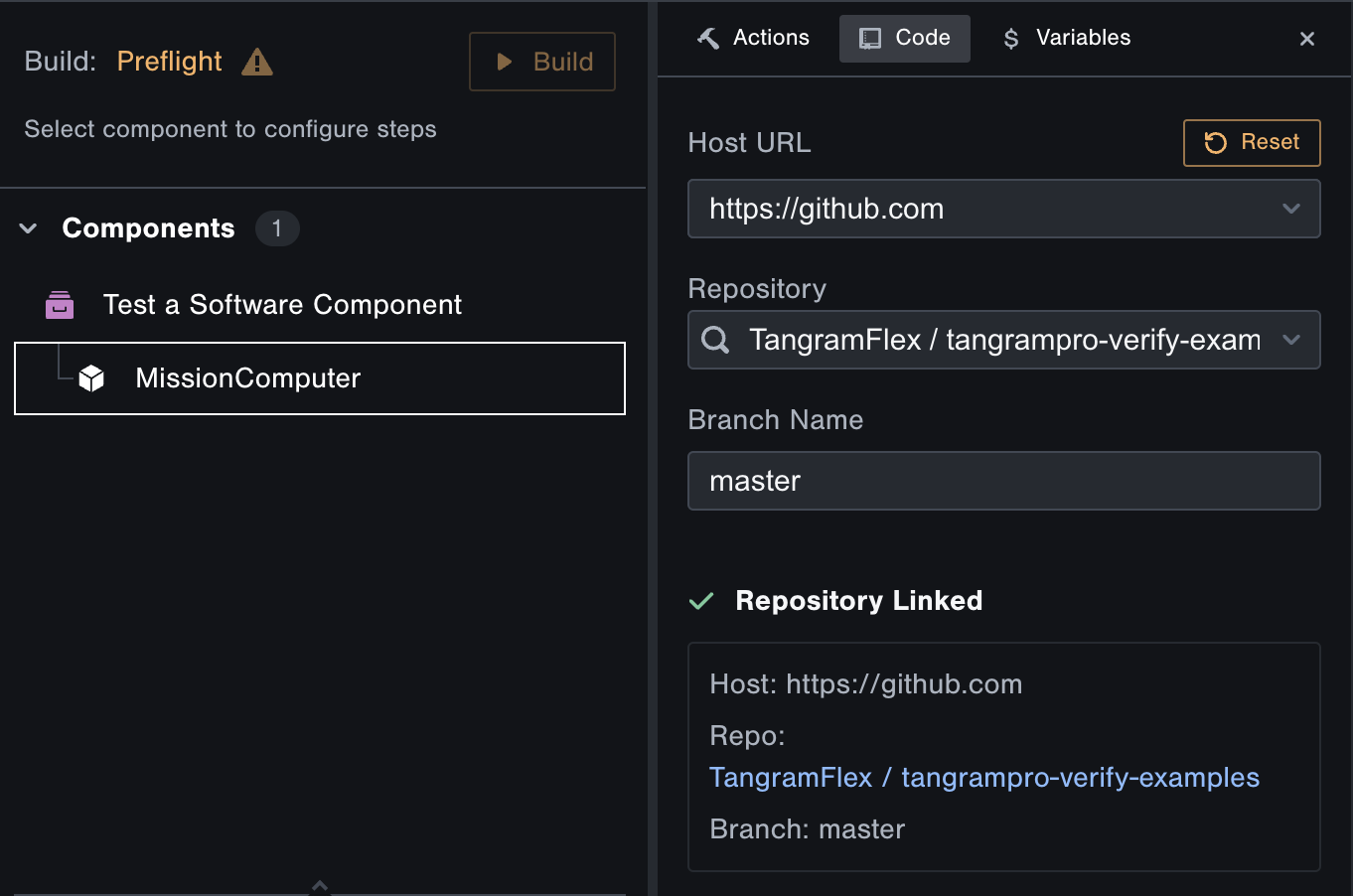
- Select the "MissionComputer" component on the left
Link the example GitHub repository to the component:
- Click the Code tab
- For Host URL choose
https://github.com(this is what you setup at the beginning) - For Repository type in the following name
tangrampro-verify-examplesand select it - The Branch Name will auto-populate with
master. Keep that as is.
Step 6: Create Test Sequences
Nice work! Now let's enter Verify mode and start definining our test sequences.
- Click Verify on the top left
- Select the "MissionComputer" component on the left if it's not already selected
- Click the Component Sequences tab
A sequence is an ordered list of messages that will be input to your component-under-test, and messages that are expected to be output by it. You can add multiple sequences to cover as many test scenarios as you need.
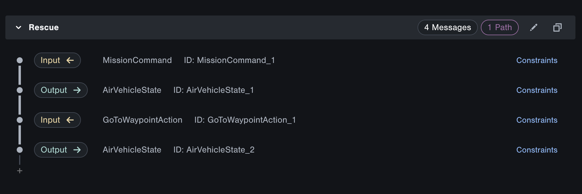
Let's start by adding the following "Rescue" mission sequence, which our software component should support.
- Our component receives a
MissionCommandfrom a control station - Our component reports the UAV's location in 3D space via an
AirVehicleStatemessage - Our component receives a
GoToWaypointActioncommand to fly the UAV to a new location - Our component again reports an
AirVehicleStateto send updated UAV location data
To add this sequence:
- Add a new sequence by clicking the Add Sequence button
- Name it "Rescue"
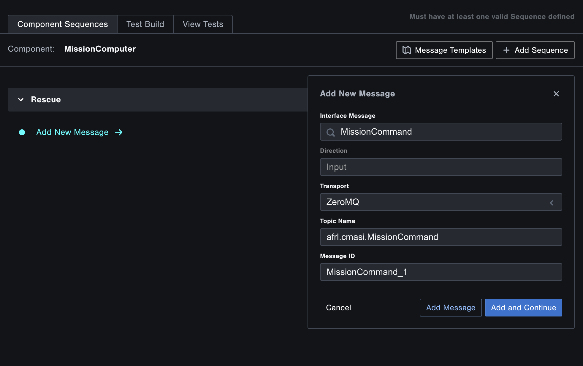
- Click the Add Initial Message button
- For Interface Message choose
MissionCommmand. It will default toInputsince we specified that direction in the design. - Keep all other fields as their defaults and click Add and Continue
- Add the following messages:
AirVehicleStateGoToWaypointActionAirVehicleState
Your Rescue sequence should like this:
Now let's add the following "Scan" mission, which our software component should also support.
- Our component receives a
CameraActionfrom a control station - Our component reports the UAV camera's
CameraConfigurationmessage - Our component receives another
CameraActioncommand - Our component reports the UAV camera's
CameraState
To add this sequence:
- Add a new sequence by clicking the Add Sequence button
- Name it "Scan"
- Click the Add Initial Message button
- For Interface Message choose
CameraAction - Keep all other fields as their defaults and click Add and Continue
- Add the following messages:
CameraConfigurationCameraActionCameraState
Your Scan sequence should like this:
Step 7: Define Rescue Constraints
Each message in a sequence can have constraints. By adding constraints, messages can be called "valid" or "invalid" based on their contents, including how the messages of one field relate to a message that came previously in a sequence.
Let's add field constraints to the messages in the Rescue sequence.
Add a Message Template
- Click the Message Templates button located in the top right corner to access your templates.
- Click Add Message Template to create a new template.
- Select
OpenUxAS::LMCP::v3for the Package. - Choose
Waypointfor the Message. - A default Template Name will be generated; however, rename it to WptItem for clarity.
- Copy and paste the following YAML configuration, then click Save Template and close the window:
- name: Number
  valid_values:
    - value: 0
- name: Latitude
  valid_values:
    - range: {min: 19.50139, max: 64.85694}
- name: Longitude
  valid_values:
    - range: {min: -161.75583, max: -68.01197}
This template specifies valid ranges for the fields Number, Latitude, and Longitude within the Waypoint message structure, which will be used as input for your component. The latitude and longitude ranges encompass the continental US.
Add Field Constraints for MissionCommand
- Click Constraints next to
MissionCommand - Copy and paste the following YAML, then click Save
- name: FirstWaypoint
  valid_values:
    - value: 0
- name: WaypointList
  valid_values:
    - indices: { 0: WptItem }
Since MissionCommand is an input, these constraints are controlling what values that will be input to our component.
Add Field Constraints for GoToWaypointAction
- Click Constraints next to
GoToWaypointAction - Copy and paste the following YAML, then click Save
- name: WaypointNumber
  valid_values:
    - value: MissionCommand_1.WaypointList.0.Number
Since GoToWaypointAction is also an input, these constraints are controlling what values that will be input to our component. By referencing MissionCommand_1, you're able to pull in data from the MissionCommand message at the beginning of the sequence.
Add Field Constraints for AirVehicleState
- Click Constraints next to the second
AirVehicleState(AirVehicleState_2) - Copy and paste the following YAML, then click Save
- name: Location.Latitude
  valid_values:
    - value: MissionCommand_1.WaypointList.0.Latitude
- name: Location.Longitude
  valid_values:
    - value: MissionCommand_1.WaypointList.0.Longitude
AirVehicleState is an output, so when we run the test, Tangram Pro will check the field values sent by our software component and verify it fits within these constraints.
Step 8: Define Scan Constraints
Next, let's add constraints to two of the messages in the Scan sequence.
Add Field Constraints for CameraConfiguration
- Click Constraints next to
CameraConfiguration - Copy and paste the following YAML, then click Save
- name: MinHorizontalFieldOfView
  valid_values:
    - range: {min: 20, max: 150}
- name: MaxHorizontalFieldOfView
  valid_values:
    - range: {min: MinHorizontalFieldOfView, max: 150}
CameraConfiguration is an output, so when we run the test, Tangram Pro will check the field values sent by our software component and verify it fits within these constraints.
Add Field Constraints for CameraAction
- Click Constraints next to the second
CameraAction - Copy and paste the following YAML, then click Save
- name: HorizontalFieldOfView
  valid_values:
    - range: {min: CameraConfiguration_1.MinHorizontalFieldOfView, max: CameraConfiguration_1.MaxHorizontalFieldOfView}
CameraAction is an input, so these constraints are controlling the values that will be input to our component, making sure it fits within the range of what our software component expects. For reference check out the logic in the source code here
Step 9: Run Tests
Great work! Now let's run these tests.
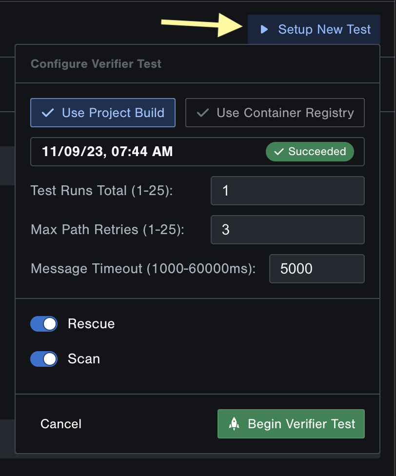
- Click the Setup New Test button.
- Select Use Container Registry option, you will need to ensure that your registry is configured. See User Guide: Container Registrises
Container registry host: ghcr.io
Path to the image: ghcr.io/tangramflex/tutorial-mission-computer:latest
- Keep all other options set as the defaults. For more information about these options see User Guide: Verify
- Click Begin Verifier Test
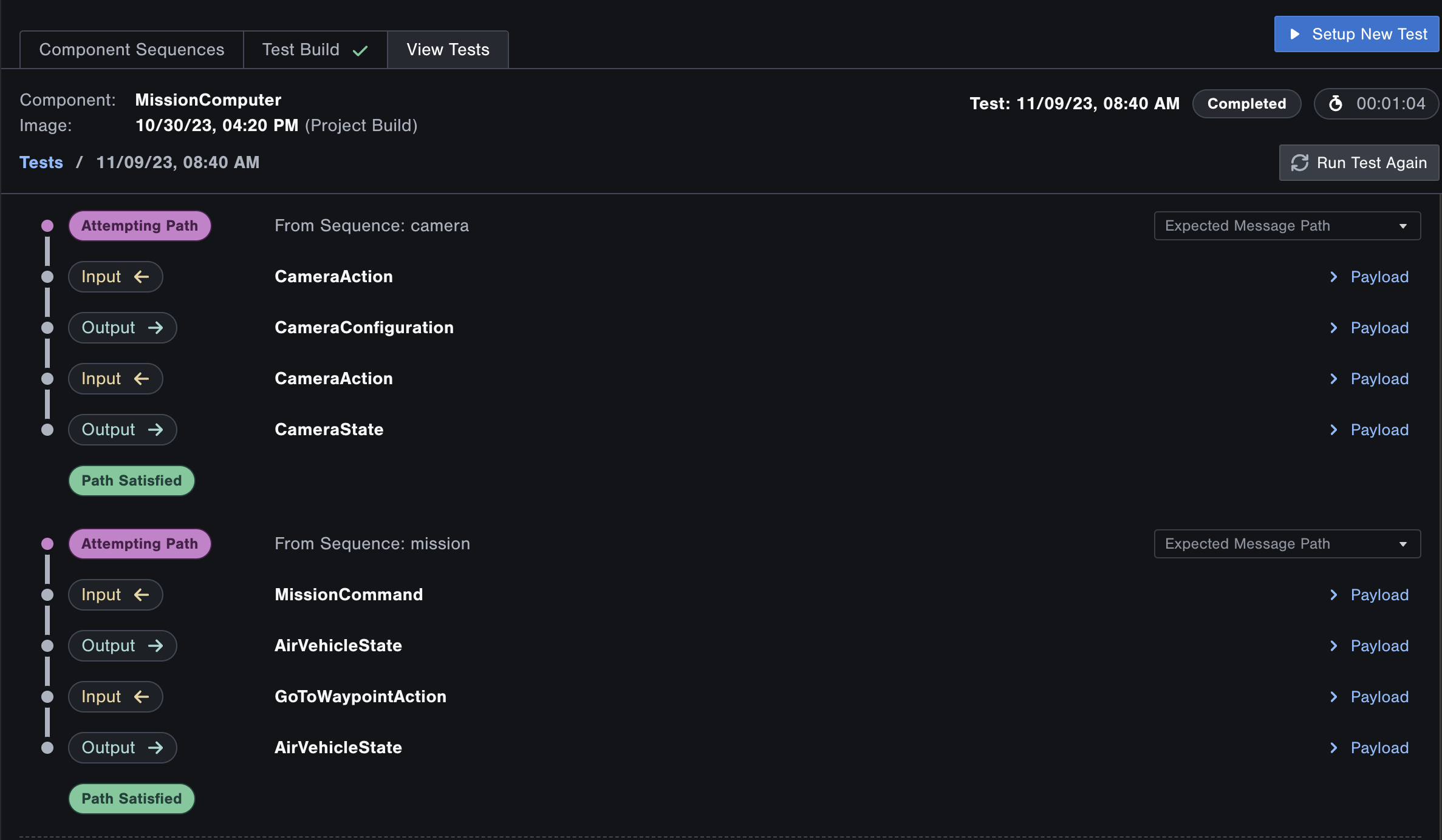
When a test is running, Tangram Pro provides live reporting as it processes and analyzes each sequence, including the contents of the messages being sent. When complete, the test summary is saved for you to view all of those details later.
Note: If a Timeout occurs, try running the test again.
Success! The two missions that our software component was expected to support have been verified!
How to read the results
Tangram Pro reports a sequence as "Satisfied" if both of these conditions are met:
- The messages were sent and received in the order specified by sequences
- The message contents met all specified constraints
A sequence will be "Unsatisfied" if either of the above conditions are not met. It is important to note, a sequence may be "Unsatisfied" if the wait time between subsequent messages exceeds the "Message Timeout" and if the number of retries reaches the "Max Path Retries".
Tangram Pro also provides two real-time log streams.
- Component Logs: These are the logs output by your software component
- Debug Logs: These are the logs output by Tangram Pro's test environment
To view previous tests
- Go to View Tests
- Click on a test to view its results in more detail
What does an "Unsatisfied" test look like?
- Try adding add another message to one of the sequences, and run the test again.
- Try removing a constraint, and run the test again.
Cheers!
By completing this tutorial, you've learned how to use the Verify tool in Tangram Pro to test a software component against a message sequence model.
Check out what you accomplished:
- Linked a component to GitHub repository
- Defined test sequences and message field constraints
- Linked a verifier test to Github registry
- Verified the two missions are supported by our software component
