Autonomous UAV Navigation
Scenario
You've just started as an Integration Engineer at SkyShield, a small startup in the electronic warfare space serving the Air Force. SkyShield produces a UAV with an autonomous navigation system. This system consists of a MissionComputer capable of controlling a Sensor, which can identify flying entities and geo-locate them. There's also a SatNav GPS receiver which provides precise location data to the system.
After thorough testing, a susceptibility was found in their SatNav components where the GPS satellite connection can get jammed causing Sensor data to go off track. For the sensor to operate correctly, it needs to know the precise location of the UAV.
To fix this issue, your team is testing an integration with an alternative navigation component produced by Acme Co. which doesn't rely on GPS. In the case where SatNav is jammed, the UAV could fall back to data from Acme's AltNav component, and the Sensor data would stay on track. This allows the mission system to continue operation seamlessly.
However, Acme's components use their own proprietary messages, whereas SkyShield's UAVs use the LMCP standard. Your team is evaluating the effectiveness of an integration tool like Tangram Pro to help them integrate and test these systems.
In this tutorial you'll learn how to:
- Design a component-based UAV navigation system using LMCP
- Integrate a proprietary component with LMCP using Flex code
- Link test applications from a GitHub repository
You'll need a GitHub account to complete this tutorial.
Design a UAV Navigation System
1. Create a Project
To begin modeling a system we need to make a project. Projects are used to design component-based systems. Let's get started!
- Go to Projects and click New Project
- Enter a Project Name
Autonomous UAV - Set the Owner to a team, or keep
Personal (You)selected
2. Add UAV Navigation Components
The autonomous UAV system we're modeling uses 3 components to process navigation data. Let's add them to the design.
- Add three components using the Add Component button
- Double-click on the component's name and enter the following names:
| Name | Purpose |
|---|---|
MissionComputer | Main hub for processing mission navigation data |
SatNav | Provides UAV position and velocity data from GPS satellite |
Sensor | Identifies flying entities and provides their geo-location |
3. Add Transport
Now let's define a transport for this design. The UAV system we're modeling is connected to a ZeroMQ transport, which handles distributing serialized messages between its components.
- Click the Transports button and add ZeroMQ
Connections in the design will now default to ZeroMQ.
4. Add Messages and Connections
Now let's define which LMCP messages are input or output by these components.
Update SatNav
-
Click the ... icon in the
SatNavcomponent and choose Messages -
Select Package
OpenUxAS::LMCP::v3 -
Add the following messages:
Message Direction AirVehicleStateOutput -
Draw a connection from
SatNavtoMissionComputerby clicking and dragging from the edge ofSatNav -
Edit the connection and choose Suggested Message
AirVehicleState
Update Mission Computer
-
Edit the Messages for
MissionComputer -
Choose Interface Package
OpenUxAS::LMCP::v3and add the following messagesMessage Direction GimbalAngleActionOutput GimbalScanActionOutput AirVehicleStateInput/Output Change AirVehicleState from Input to Input/Output
Update Sensor
-
Edit the Messages for
Sensor -
Choose Interface Package
OpenUxAS::LMCP::v3and add the following messagesMessage Direction EntityStateOutput -
Draw a connection from
SensortoMissionComputer, edit it and choose Suggested MessageEntityState -
Click Switch Directions and choose the following messages:
AirVehicleStateGimbalAngleActionGimbalScanAction
Nice work! You design should look similar to this:
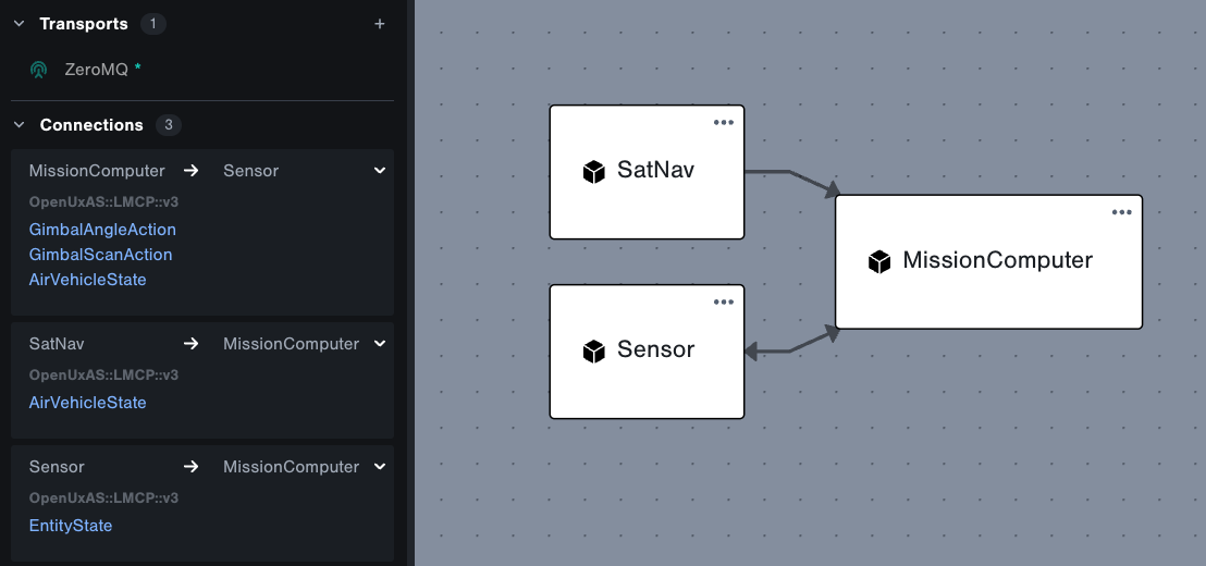
Expand the Connections section on the left to quickly examine interface connections.
Group, Layout and Tag
There are additional features available to help you organize and filter your designs. You can group and tag components, and change the direction of the layout.
1. Add a Group
Let's group the components that use LMCP messages for more visual clarity.
- Click the Add Group button in the design toolbar and click anywhere on the stage to add it
- Double-click on the groups's name and enter
LMCP - Drag the
MissionComputer,SatNavandSensorcomponents into the group
The layout automatically adjusts as components are added to or removed from a group
Try collapsing the group by clicking the – icon in the top left, and expand by clicking the + icon
2. Adjust Layout
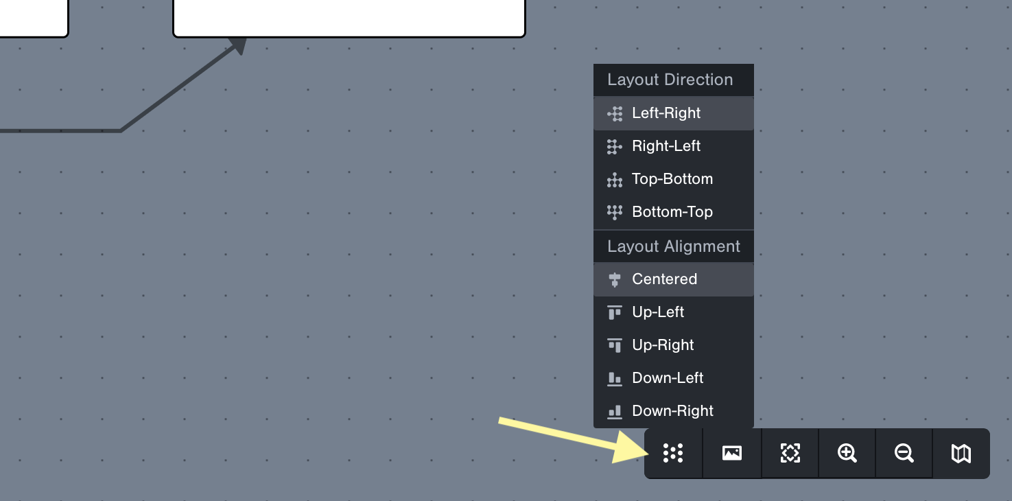
You can change the direction and alignment of connections by clicking the Layout button in the bottom right toolbar.
3. Add Tags
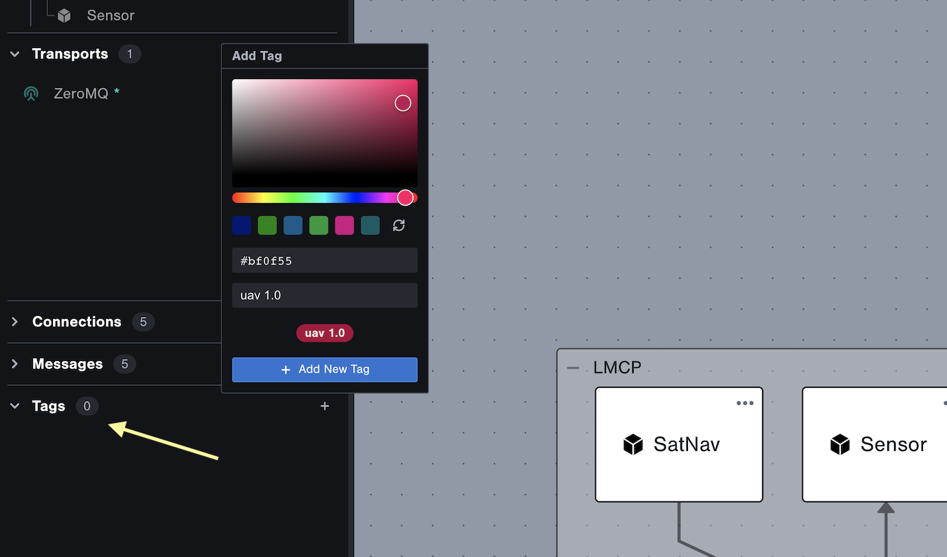
Tangram Pro also allows you to tag components with a color and label. Let's use tags to designate which UAV version the components belong to.
Add tags to the project
- Expand the Tags section in the bottom left
- Click the + to add a tag.
- Choose a color and enter name
uav 1.0 - Add another tag with a different color and enter name
uav 2.0(we'll use this later)
Apply tags to components
- Select the
MissionComputercomponent in the design and click the ... button - Click Edit Tags and select
uav 1.0 - Apply the same tag to the
SatNavandSensorcomponents
So far you've:
- Created a valid design of SkyShield's autonomous UAV navigation system
- Defined the interfaces / connections for each component using LMCP messages
Integrate Alternative Navigation
The current UAV navigation system relies on a GPS satellite connection to provide the UAVs current location to the mission computer. The mission computer then sends this information periodically to the gimballed sensor so it is able to locate the tracks. If the GPS receiver becomes "jammed", then it will occasionally fail to update its location. This bad data causes the sensor to incorrectly locate the tracks
Next we're going to integrate Acme's AltNav component into the design, and test interfacing with its navigation data when SatNav is jammed.
1. Add Custom Flex Message
This component doesn't use LMCP, but we can easily define a custom message type using Flex.
- Go to Flex Packages in the upper right menu, and click Open Flex Editor
- Click Package Manager and create a package named
AcmeEngineering::v3 - Hover over your package on the left, and add a file named
AltNav.flex - Paste the following code in the file:
message struct AltNavPosition
{
    timestamp : int64;
    lat: float64;
    lon: float64;
    alt: float32;
}- Save the file using (Cmd + S / Ctrl + S)
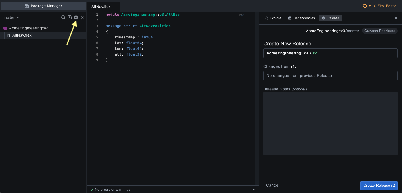
- Create a release by clicking the checkmark icon above the package name, and clicking the Create Release button
2. Add Custom Flex Transform
Next we'll need to define a transform function to handle the conversion of Acme's AltNavPosition
to LMCP AirVehicleState.
- Click Package Manager and create a new Flex package named
Transforms::AcmeEngineering::v1 - Add a file named
AltNav2LMCP.flexand enter the following code:
import AcmeEngineering::v3.AltNav (AltNavPosition)
import OpenUxAS::LMCP::v3.afrl.cmasi(AirVehicleState, AltitudeType, NavigationMode, Location3D)

transform ANP2AVS(alt : AltNavPosition) -> AirVehicleState {
    let location = Location3D {
        Latitude = alt.lat;
        Longitude = alt.lon;
        Altitude = alt.alt;
        AltitudeType = AltitudeType.MSL;
    };
    AirVehicleState {
        ID = 0;
        u = 0.0;
        v = 0.0;
        w = 0.0;
        udot = 0.0;
        vdot = 0.0;
        wdot = 0.0;
        Heading= 0.0;
        Pitch=0.0;
        Roll=0.0;
        p=0.0;
        q=0.0;
        r=0.0;
        Course = 0.0;
        Groundspeed = 0.0;
        Location = location;
        EnergyAvailable = 0.0;
        ActualEnergyRate = 0.0;
        PayloadStateList = [];
        CurrentWaypoint = 0;
        CurrentCommand = 0;
        Mode= NavigationMode.Waypoint;
        AssociatedTasks = [];
        Time = alt.timestamp;
        Info = [];
        Airspeed = 0.0;
        VerticalSpeed = 0.0;
        WindSpeed = 0.0;
        WindDirection = 0.0;
    };
}- Save the file using (Cmd + S / Ctrl + S)
- Add package dependencies for the import statements by clicking the box icon above the package name
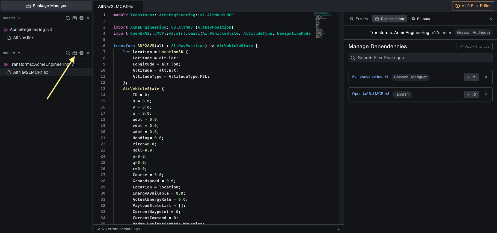
- On the right, search for and add these 2 Flex Packages. Click Apply Changes after they're added.
AcmeEngineering::v3OpenUxAS::LMCP::v3
- Create a release of your Transform package by clicking the checkmark icon above the package name, and clicking the Create Release button
- Close the Flex Editor by clicking the x in the top right to return to the design
3. Connect AltNav with a Transform
Next we'll add a component to represent Acme's AltNav in the design, and use the Flex packages you released. The AltNav component outputs Acme's AltNavPosition messages, but MissionComputer expects LMCP AirVehicleState messages. Let's add a transform object to the design to handle this conversion.
- Add a new component named
AltNav - Edit its Messages and choose
- Package:
AcmeEngineering::v3 - Message:
AltNavPosition - Direction:
Output
- Package:
- Click the Add Transform button in the design toolbar and click anywhere on the stage to add it
- Now select which components connect to the transform. Click on
AltNavfirst thenMission_Computer - For the Input Message, use the Suggested button to choose
AltNavPosition - For the Output Message, use the Suggested button to choose
AirVehicleState - Apply the
ANP2AVStransform - Next we'll specify the transport and serializer for both sides of the transform application that we'll generate in the next section
- For the Input Message choose:
- Transport:
ZeroMQ - Serializer:
Direct
- Transport:
- For the Output Message choose:
- Transport:
ZeroMQ - Serializer:
LMCP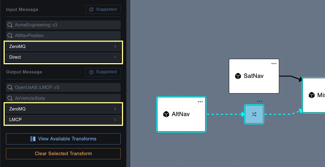
- Transport:
- Close the transform settings by clicking in any empty area in the design
Great! You've integrated the AltNav component into the design. Now let's explore additional design features.
4. Tag AltNav
Let's tag the AltNav component:
- Select the
AltNavcomponent and Edit Tags - Apply the
uav 2.0tag
You can filter the design view based on tags:
- Hover over a tag in the list to highlight the tagged components in the design
- Click the eye icon next to a tag to filter the design to only the tagged components
Cheers!
You've completed a successful test of the AltNav integration using Tangram Pro 🎉
Check out what you accomplished:
- Designed a component-based UAV navigation system
- Integrated a proprietary component using Flex code